1. Abstract & Project Objective
This project presents the design, analysis, and validation of a compact 6-speed Dual-Path Dedicated Hybrid Transmission (DHT) system aimed at addressing key limitations in conventional automatic transmissions used in mid-size hybrid SUVs. Traditional systems suffer from shift shock, increased mechanical complexity, and packaging constraints, particularly when integrating both internal combustion engine (ICE) and electric vehicle (EV) power sources.
To address these challenges, a dual-path architecture is proposed, enabling independent yet coordinated, simultaneous power delivery from both ICE and EV sources to a common output shaft. This configuration eliminates the need for conventional shifting mechanisms (relying on clutches and synchronizers), minimizing shift shock and enhancing system smoothness.
2. Design Requirements & Boundary Conditions
The transmission system is governed by a set of requirements derived from realistic operating conditions of a mid-size hybrid vehicle:
- Baseline Torques: 172 Nm for the Internal Combustion Engine (ICE) operating at 3000 RPM, and 205 Nm for the Electric Motor (EV).
- Design Loadings: An application factor of 1.25 accounts for dynamic load fluctuations, yielding effective design torque ratings:
- ICE Design Torque: 215 Nm
- EV Design Torque: 256.25 Nm
- Geometric Constraints:
- Minimum pinion tooth count \(Z_1 \ge 18\) to prevent gear undercutting and maintain tooth root strength.
- Standard metric gear modules (m) in the range of 1.5 mm to 3.5 mm.
- Permissible ratio deviation of \(\pm 5\%\) from the target gear ratios.
- All gear stages must operate under a **common center distance** (\(a\)) to enable a compact, coaxial layout within a single housing.
3. Kinematic Design Methodology
Due to the discrete nature of gear teeth and the constraint of a uniform center distance, selecting gear profiles manually is highly inefficient. Therefore, we developed a Python-based optimization algorithm to systematically search the design space:
DEFINE Standard Modules = [1.5, 2.0, 2.5, 3.0]
DEFINE Target Ratios = [ICE 1: 3.5, ICE 3: 1.1, EV Sleeve: 3.5]
DEFINE Minimum Pinion Teeth (Z1) = 18 // To prevent undercutting

START OPTIMIZATION:
FOR EACH Module in Standard Modules:
    CREATE empty database to group gears by their Center Distance (a)
    FOR EACH Pinion Tooth Count (Z1) from 18 to 100:
        FOR EACH Target Ratio:
            // 1. Synthesize driven gear
            CALCULATE Z2 = Z1 * Target Ratio
            ROUND Z2 to nearest whole number of teeth

            // 2. Validate geometry
            IF actual ratio (Z2 / Z1) is within a 5% tolerance:
                CALCULATE Center Distance (a) = Module * (Z1 + Z2) / 2
                // 3. Log results
                SAVE gear pair (Z1, Z2) under Center Distance (a)

    // 4. Coaxial Cross-Check
    SEARCH database for any Center Distance (a) that contains valid gears for ALL three targets.
    IF a universal match is found:
        PRINT "Optimal Architecture Found"
        PRINT Center Distance, Module, and exact tooth counts
        STOP SEARCH
4. Gear Design Calculations & Root Stress Analysis
The structural integrity of candidate gear configurations is validated using the **Lewis Bending Stress** equation.
Trial Iteration (Unsafe Configuration):
We first evaluated a compact trial design using a module of \(m = 1.5 \text{ mm}\). We analyzed the weakest link: the **ICE 1 Pinion Gear** (\(Z_1 = 20, m = 1.5 \text{ mm}\)):
- Pitch Circle Diameter (\(d\)): \(d = m \times Z_1 = 1.5 \text{ mm} \times 20 = 30 \text{ mm} = 0.03 \text{ m}\)
- Face Width (\(b\)): Standard practice of \(10m = 15 \text{ mm} = 0.015 \text{ m}\)
- Lewis Form Factor (\(Y\)): For a 20-tooth gear, \(Y \approx 0.32\)
- Tangential Load (\(W_t\)): Calculated from the ICE design torque (215 Nm): \[W_t = \frac{T_{\text{design}}}{d / 2} = \frac{215 \text{ Nm}}{0.015 \text{ m}} = 14,333 \text{ N}\]
Substituting these values into the Lewis stress equation:
\(\sigma_b = \frac{W_t}{b \times m \times Y} = \frac{14,333 \text{ N}}{0.015 \text{ m} \times 0.0015 \text{ m} \times 0.32} = 1,990.7 \text{ MPa}\)
A standard high-grade, case-hardened alloy gear steel (such as 15Ni2Cr1Mo28) has an allowable bending stress limit (\(\sigma_{b,\text{allow}}\)) of **400 to 450 MPa**. The trial stress of **1,990.7 MPa** significantly exceeds this threshold, meaning the gear teeth would shear off instantly.
Optimized Design (Safe Configuration):
To resolve this, we increased the module to \(m = 2.5 \text{ mm}\), widening the gear teeth and scaling load capacity. Recalculating with the updated dimensions, the induced bending stress falls to **397 MPa**, which lies safely within the permissible material limits.
The optimization algorithm returned a common center distance of **118.75 mm** using a module of **2.5 mm**.
| Gear Pair Regime | Pinion Teeth (\(Z_1\)) | Gear Teeth (\(Z_2\)) | Actual Ratio | Target Ratio | Center Distance (\(a\)) |
|---|---|---|---|---|---|
| ICE 1 (Heavy Load) | 21 | 74 | 3.52 | 3.50 | 118.75 mm |
| ICE 3 (Highway) | 41 | 50 | 1.22 | 1.10 | 118.75 mm |
| EV 1 Sleeve (Launch) | 21 | 74 | 3.52 | 3.50 | 118.75 mm |
The final optimized set of achieved gear ratios covers a wide operating spectrum: 3.52, 2.05, 1.38, 1.00, 0.82, and 0.65.
5. Simulation Setup & Kinematic Validation
To validate the functional behavior of the proposed dual-path transmission system, a simulation model was developed in MATLAB/Simulink. The model replicates the interactions between the gear trains, shafts, and power sources.
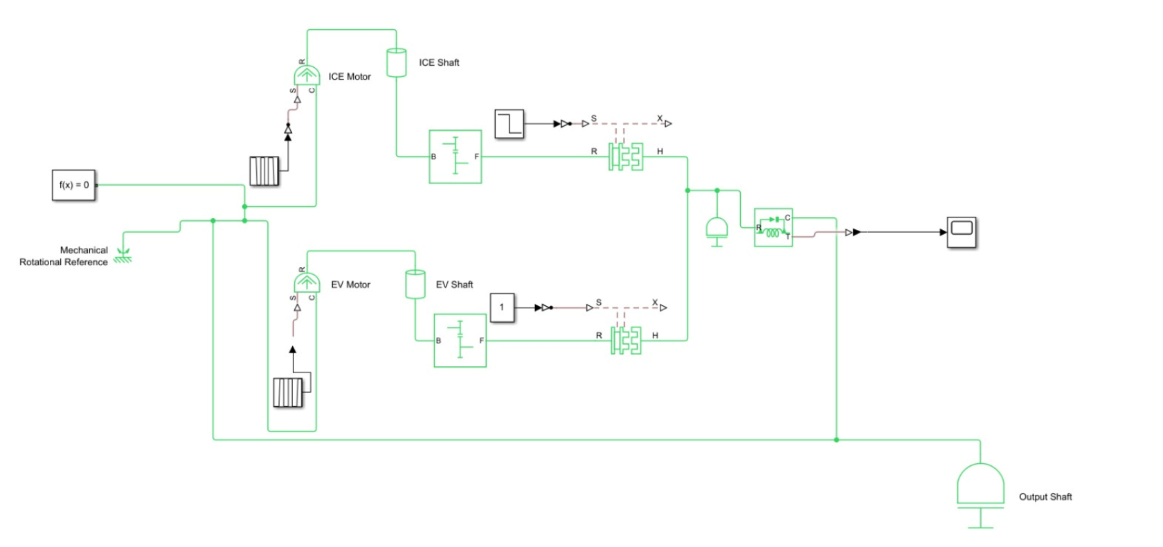 Figure 1: Complete Simulink block model of the dual-path transmission showing compound planetary carriers and clutching nodes
The simulation applies a rotational input of 3000 RPM to both the ICE and EV input shafts. The motion transfer was verified across the gear train:
- Directional Reversal: The countershaft exhibits a rotational speed of approximately **-851 RPM**, with the negative sign indicating the expected reversal in direction due to gear meshing. This confirms correct gear engagement.
- Rotational Stability: The output shaft demonstrates stable and continuous rotation, confirming the absence of binding, interference, or speed fluctuations under dynamic blending.
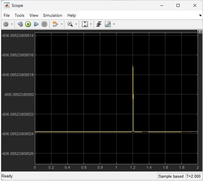 Figure 2: Simulation output scope displaying shaft speeds and smooth transition curves
6. Dynamic Vehicle Performance Analysis
The dynamic performance of the proposed dual-path transmission was evaluated by modeling vehicle physics under representative driving conditions. The modeling parameters are:
- Vehicle Mass (\(M\)): 1800 kg
- Aerodynamic Drag Coefficient (\(C_d\)): 0.32
- Wheel Radius (\(r\)): 0.35 m
- Estimated Transmission Efficiency (\(\eta\)): 85% (accounting for meshing and churning losses)
The vehicle simulations demonstrate stable torque delivery during launches and highway cruises, maintaining progressive distribution of gear ratios and smooth transitions.
7. Interactive Simulation & Synthesis Tools
To visualize, analyze, and test the kinematic limits of this 6-Speed Dedicated Hybrid Transmission, we developed two custom web-based simulation tools deployed using Python and Streamlit.
1. GearGraph: Universal Synthesizer
GearGraph serves as an interactive matrix linear constraints solver for compound planetary setups. It allows users to build custom gear train layouts and inspect live velocity relationships:
- Dynamic Gearing Input: Add planetary gear sets (e.g. PG1 with Sun teeth: 30, Ring teeth: 70) and connect power sources (e.g. Engine RPM) directly on the interface.
- Linkage Definition: Wire mechanical constraints between gears (Lock Together, Lock to Power, Ground as Brake, and Spur Gear Mesh).
- Live Kinematic State: Resolves linear matrices to display live nodal speeds (e.g., Sun: 3000 RPM, Carrier: 604 RPM, Ring: -422.8 RPM) and plots global speed vectors in real-time.
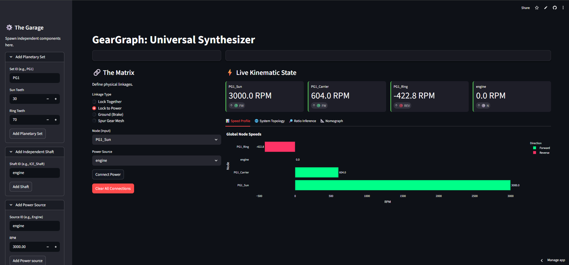 Figure 3: GearGraph Streamlit application dashboard showing live planetary kinematic connections
2. Universal Transmission Simulator (UTS)
The Universal Transmission Simulator is a transient dynamic powertrain simulator. It translates kinematic ratios into real-world vehicle performance metrics, accounting for continuous physics equations:
- Chassis & Environment Inputs: Adjust vehicle mass (1450 kg), wheel radius (0.33 m), drag coefficient (0.30 Cd), and frontal area to analyze tractive efforts.
- Performance Insights: Models vehicle launch and acceleration parameters, outputting key stats (0-100 km/h: 4.58 seconds, 0-60 km/h: 2.4 seconds, top speed: 369.4 km/h, peak acceleration: 0.93 G, engine peak power: 337 HP).
- 0-100 Physics Run Matrix: Plots real-time vehicle speed and acceleration (G) curves versus elapsed time.
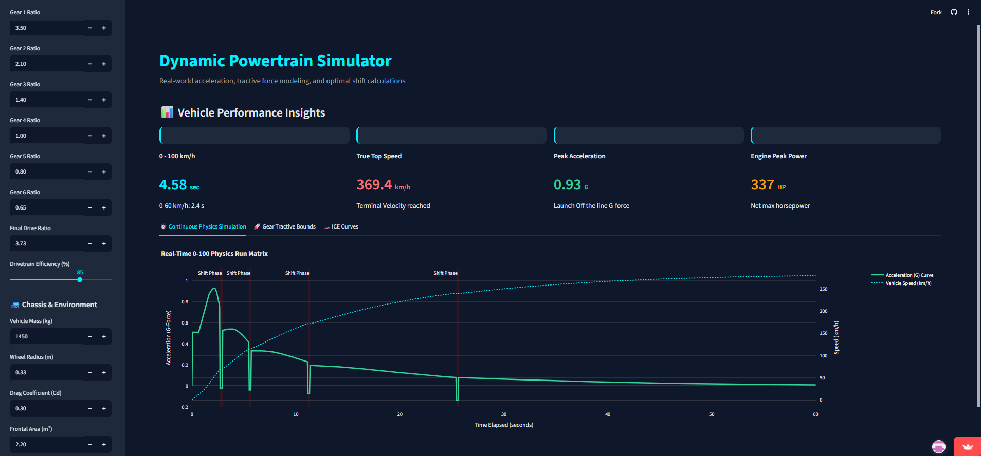 Figure 4: Universal Transmission Simulator Streamlit dashboard displaying vehicle tractive forces and real-time transient physics acceleration curves
Kinematic & Structural Innovation Summary
By employing algorithmic kinematic search and verifying gear geometries using Lewis bending stress checks, this project achieves a structurally safe, 6-speed transmission within the physical space envelope of a standard 3-speed DHT, minimizing weight and packaging complexity.