Key Projects Undertaken during the Internship
Project 1: Redesign of Support Wheel for SAFOP Lathe
The heavy-duty SAFOP CNC lathe, used for machining large APH rotor posts and shafts, was experiencing unstable operations due to a worn-out tailstock support wheel. The original rubber lining on the support wheel had degraded over time from continuous exposure to mechanical abrasion and cutting fluids.
Using a vernier caliper, I reverse-engineered the core dimensions. I developed a detailed SolidWorks 3D CAD model and manufacturing drawings to outline a modular replacement. The updated design incorporates a high-strength aluminum cast alloy hub lined with a 94-95 Shore A Polyurethane (PU) coating, running on dual 6204 ZZ bearings. Once fitted, carriage vibrations were eliminated, restoring smooth tailstock guidance.
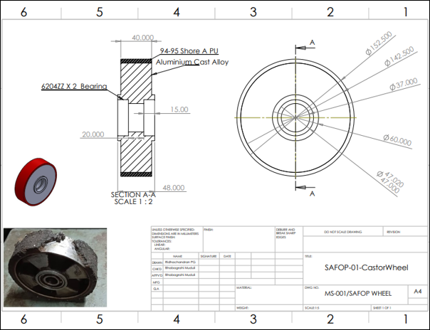 Figure 1: SolidWorks assembly drawing of the SAFOP support wheel (152.5 mm
OD) showing bearings, polyurethane lining, and worn metal core
Figure 1: SolidWorks assembly drawing of the SAFOP support wheel (152.5 mm
OD) showing bearings, polyurethane lining, and worn metal core
Project 2: Spur Gear Redesign for DR10 Drilling Machine
A DR10 radial drilling machine suffered a gearbox failure when one of its head lock spur gears sheared its teeth under high-torque loading. Lacking the manufacturer's blueprint, I reverse-engineered the gear geometry.
By measuring the outer diameter (OD) and counting the remaining teeth (z = 36), I calculated the gear module (m) using standard sizing equations:
\(m = \frac{OD}{z + 2} = \frac{95 \text{ mm}}{36 + 2} = 2.5 \text{ mm}\)
Using these parameters, I determined the Pitch Circle Diameter (PCD) to be 90 mm (\(m \times z\)) with an 8x3 mm keyway and a bore of \(\phi 30.00 \pm 0.02\) mm. I drafted the manufacturing specifications in SolidWorks. The replacement gear was manufactured from EN353 case-hardened alloy steel, restoring the machine to operation.
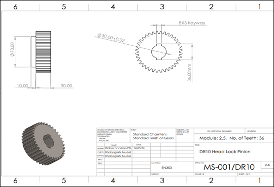 Figure 2: Head Lock Pinion gear drawing (Module 2.5, 36 teeth) with
case-hardened EN353 material specifications
Figure 2: Head Lock Pinion gear drawing (Module 2.5, 36 teeth) with
case-hardened EN353 material specifications
Project 3: Maintenance Record AI Assistant (LLM-Based Chatbot)
BHEL maintains massive Oracle database records containing breakdown logs, downtime metrics, and spare parts logs
under the MSR_SAP schema. However, querying these tables required manual SQL script writing by
database administrators.
To solve this, I designed a local AI Assistant chatbot using Python 3.10+ and Llama 3.2 (3B) run locally via Ollama. The application uses prompt engineering to translate natural language user questions into Oracle-compliant SQL queries. It performs safety validation (blocking drop/delete actions), executes the query against the database, and uses a second prompt to translate raw data tables back into conversational, text-based summaries. This tool slashed search times for historical repair queries from 30 minutes down to under 10 seconds.
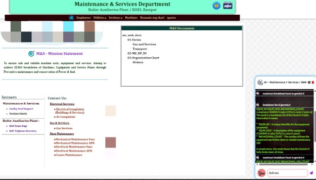 Figure
3: Web chatbot interface running local Llama 3.2
Figure
3: Web chatbot interface running local Llama 3.2
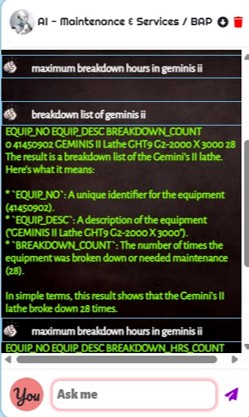 Figure
4: Chatbot SQL generation and execution terminal log
Figure
4: Chatbot SQL generation and execution terminal log
Project 4: Design and Analysis of a Hybrid Jaw Puller for De-coiler (HE Line)
On the Heavy Engineering (HE) Line, the decoiler uncoils heavy steel coils to feed APH element and ESP plate roll-forming lines. The clamping jaws (gripping the inner diameter of the coil) were made of a single-piece cast bronze. Under intense cyclic clamping force, the bronze jaws suffered brittle fracture failures and rapid friction-induced wear, leading to high replacement costs and weeks of plant downtime.
I proposed a modular **Hybrid Jaw** redesign. It consists of a structural ASTM A36 steel body for high stiffness and load-carrying capacity, coupled with replaceable Phosphor Bronze wear pads that contact the steel coil. This ensures high grip friction without risking structural failure or damaging the uncoiler shaft.
| Feature | Original (Full Bronze) | New (Hybrid: Steel + Bronze) |
|---|---|---|
| Material Class | Entirely Bronze (Single Cast) | Body: ASTM A36 Steel | Inserts: Phosphor Bronze |
| Replaceability | Replace complete jaw assembly | Only swap out worn bronze inserts |
| Component Cost | High manufacturing/casting cost | Lower (cheap structural steel body) |
| Maintenance Downtime | Long (several weeks to cast new jaw) | Short (hours to swap inserts on-site) |
| Wear Performance | Good | Same (matching contact surface interface) |
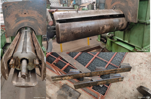 Figure 5: Failed single-piece cast bronze decoiler jaw (showing fracture
surface) and uncoiler mandrel shaft
Figure 5: Failed single-piece cast bronze decoiler jaw (showing fracture
surface) and uncoiler mandrel shaft
I built the 3D assembly in SolidWorks and performed Finite Element Analysis (FEA) to validate the stress distribution under peak clamping loads.
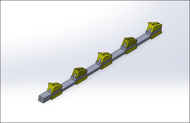 Figure 6: SolidWorks assembly model showing modular steel carrier body and 5
bolted bronze inserts
Figure 6: SolidWorks assembly model showing modular steel carrier body and 5
bolted bronze inserts
The FEA model utilized tetrahedral elements (with refined contact meshes) and simulated the boundary conditions (mandrel shaft constraints and radial coil load). The analysis computed Von Mises stress, displacement (deformation), and strain profiles:
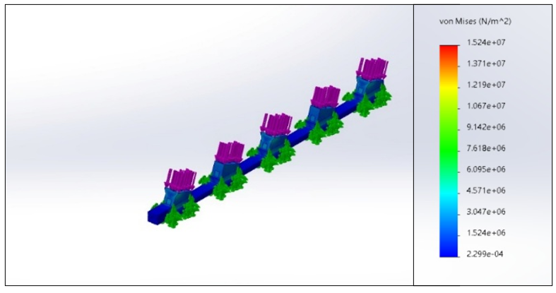 Stress
Plot (Von Mises)
Stress
Plot (Von Mises)
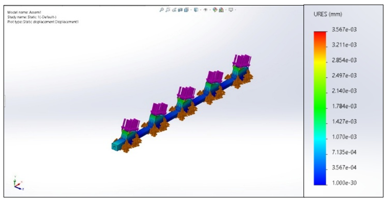 Displacement
Plot
Displacement
Plot
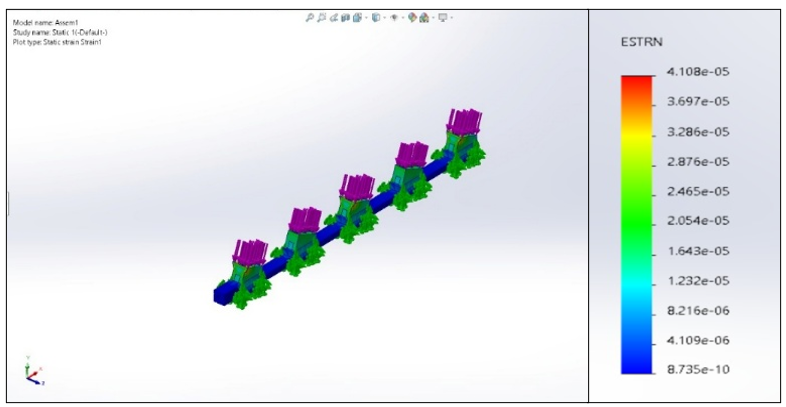 Elastic
Strain Plot
Elastic
Strain Plot
| FEA Parameter | Observed Value | Material Safe Limit | Status |
|---|---|---|---|
| Max Stress (Steel Body) | 2.299e+04 N/m² (\(\approx 0.023\) MPa) | ≤ 250 MPa (ASTM A36 Yield) | Safe |
| Max Stress (Bronze Insert) | 2.299e+04 N/m² (\(\approx 0.023\) MPa) | ≤ 145 MPa (Phosphor Bronze Yield) | Safe |
| Max Deformation (Displacement) | 2.140e-03 mm | Negligible (fraction of a micron) | Acceptable |
The FEA simulation confirms that the modular steel body remains far below its yield limits, avoiding plastic deformation. The bronze inserts operate under a very high safety factor, ensuring high wear resilience. Redesigning this jaw successfully reduced component cost by 40–50% and slashed machine downtime from weeks (for full casting replacement) to just a few hours (for insert swaps).
Internship Projects Summary
This series of projects demonstrates core mechanical engineering skills across **reverse engineering** (support wheel, gear teeth calculation), **design & FEA validation** (hybrid steel-bronze uncoiler jaws), and **applied software** (Llama 3.2 local SQL AI chatbot assistant).